
 EN
EN
 English
 繁体中文
繁体中文 Italian
 Greek
Greek Spanish
 Hebrew
 Japanese
 Portuguese
 Korean
 Russian
 French
 German
 Arabic
Blog & Events
Follow NOVANEON for more valuable information to know early
Follow NOVANEON for more valuable information to know early
Aug 12Source: Views: 232
Shaping 3d bending led flex strips around sharp architectural edges requires leveraging multi-axis movement. Technicians must strictly respect a minimum bending radius of 1 inch (25 mm). They must avoid applying direct physical force onto the illuminated led surface. Manual tight folding destroys internal copper trace layers. Therefore, sharp 90-degree architectural turns demand solderless corner connectors, specialized tracks, or cut-and-connect junctions.
Achieving continuous light diffusion with led neon rope lights around corners requires proper physical handling. Installers preserve IP-rated weather seals by combining exact shaping dynamics with specialized mounting hardware. This clean installation practice ensures long-term architectural lighting performance across every edge contour.
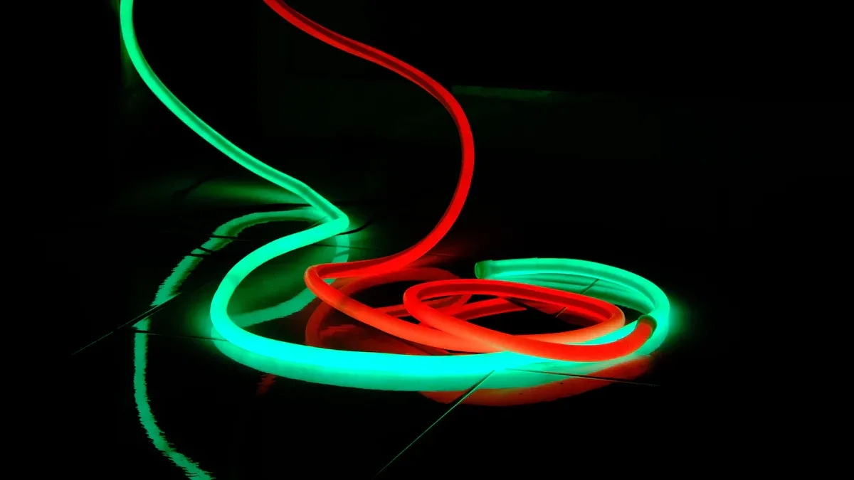
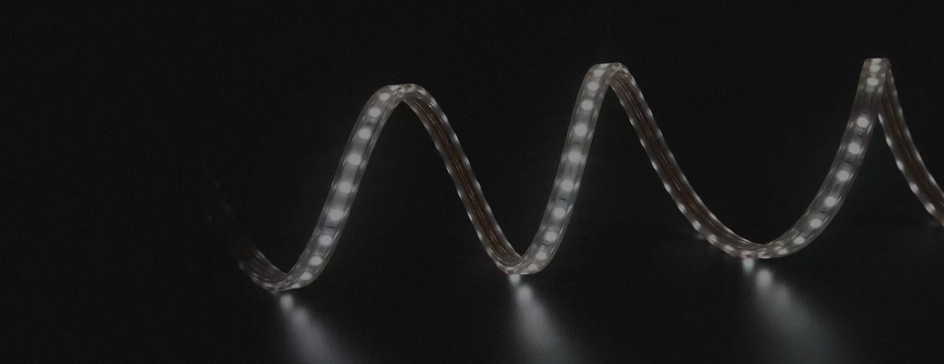
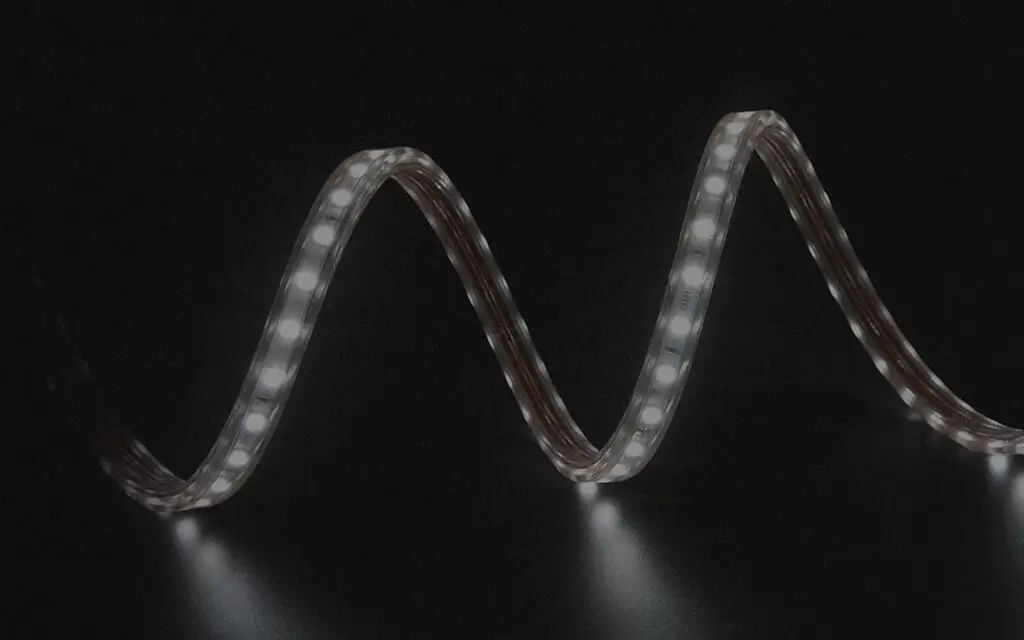
Traditional flexible led strips move along a single planar axis. Installers can only curve these conventional lights vertically. Standard designs tear internal components when twisted sideways around tight corners. In contrast, 3d bending led flex uses a specialized zig-zag PCB layout. This unique internal construction permits both lateral and vertical movement across complex architectural contours.
3D Neon Flex isn’t confined to a flat plane. It bends, twists, and turns in three dimensions, creating a stunning interplay of light that adds depth and texture to any environment.
These advanced led neon rope lights solve challenging structural layout problems. Modern lighting designers select led neon rope lights to wrap columns and trace irregular wall facades seamlessly. The specialized PCB accommodates continuous multi-directional bends. Without this engineering, forcing led neon rope lights past their native axis causes severe internal PCB damage, solder-joint cracking, and premature section failure.
Every installer must follow exact physical limits when shaping multi-axis lights around corners. Forcefully folding a flex profile over tight edges fractures delicate internal components. Installers must maintain a strict minimum bending radius of 1 inch (25 mm) during manual placement. Maintaining this spatial allowance protects internal trace layers against micro-fractures.
The governing design standard IPC-2223 and qualification testing standard IPC-6013 define strict bending guidelines for multi-layer conductors. Technicians compute physical limits using total strip thickness.
Application Type | Conductor Layers | Minimum Bend Radius Multiplier (x Total Flex Thickness) |
Static Bend | Single Layer | 6 |
Static Bend | Multilayer (2+) | 12 |
Dynamic Bend | Single Layer | 100 |
Dynamic Bend | Multilayer (2+) | 100 to 150 |
Technicians calculate exact mechanical limits before installation. Formula guidelines state: minimum bending radius = multiplier x total flex thickness. Expert installers add an extra 20-30% safety margin to this calculated bending radius to absorb handling stress. Respecting these calculations allows crew members to bend led flex strips safely without causing permanent circuit damage or optical distortion.
Technicians install led neon rope lights along architectural coves to form continuous sweeping curves. Soft ambient lighting transforms linear spaces cleanly. Installers must evaluate the physical limits of 3d bending led flex before shaping smooth arcs. Specialized products like silicone side bend profiles require a minimum bending diameter of 100 mm. This physical measurement equals a minimum bending radius of 50 mm. Bending the profile beyond this curvature threshold damages internal conductors. Controlled bending protects delicate trace layers during initial installation. Proper structural placement distributes physical tension evenly across the full profile length.
Calculating allowable sweeping arcs prevents physical stress across the flexible profile casing. Installers calculate maximum allowable curvature angles for specific arc lengths using the established minimum bend radius. Maintaining appropriate arc dimensions prevents localized strain along internal wiring paths.
· Use rigid aluminum channels or flexible mounting tracks to guide smooth curves without sagging.
· Secure led neon rope lights with spaced mounting clips to prevent localized kinks along sweeping architectural contours.
· Provide extra slack in outdoor installations to absorb ambient thermal expansion without structural strain.
Installers apply gradual bending along wall reveals to maintain uniform light diffusion. Proper track placement prevents dynamic profile displacement during thermal movement. Smooth sweeping curves require consistent clip spacing along the entire run length. Technicians position led neon rope lights into flexible tracks to follow seamless wall contours. Properly secured led neon rope lights deliver uniform brightness across large architectural features. This systematic installation method preserves optimal lighting output without creating optical shadowing.
Installers encounter tricky turns and angles when navigating physical structural boundaries. Workers must never bend led neon rope lights directly at a sharp 90-degree angle. Sharp physical folding destroys surface-mounted led components and breaks internal circuit wiring. Broken circuits create dark spots, intermittent flickering, or complete system failure. Heavy physical stress also cracks outer protective silicone casing material. Damaged outer casings create serious safety hazards like electrical short circuits.
· Right-angle connectors create a clean structural break in the profile and rejoin it at the desired angle.
· Specialized corner accessories function like plumbing corner joints to navigate sharp turns without stressing internal wiring.
· Pre-installation layout sketches help installation teams procure necessary T-connectors and right-angle accessories in advance.
Detailed planning helps installers route led neon rope lights along complex structural edges effortlessly. For standard 120V led neon rope lights, installers must respect a safe tightest curve diameter of 1 to 2 inches. Maintaining this safe bending radius prevents mechanical strain on internal components. Installers choose flexible led strips or modular corner links rather than forcing manual bending. Protecting every individual led chip prevents premature driver failure and flickering. Workers mount led neon rope lights carefully using corner accessories around tight structural junctions. Proper physical alignment prevents severe hardware damage and secures reliable long-term lighting across all interior edges.
Mounting clips and tracks distribute structural weight evenly along every corner transition. Correct hardware placement guides profiles smoothly along structural borders while preventing sagging. Technicians avoid improvising sharp turns through manual force. Following structured layout plans guarantees high visual appeal and long operational life for every commercial lighting installation.
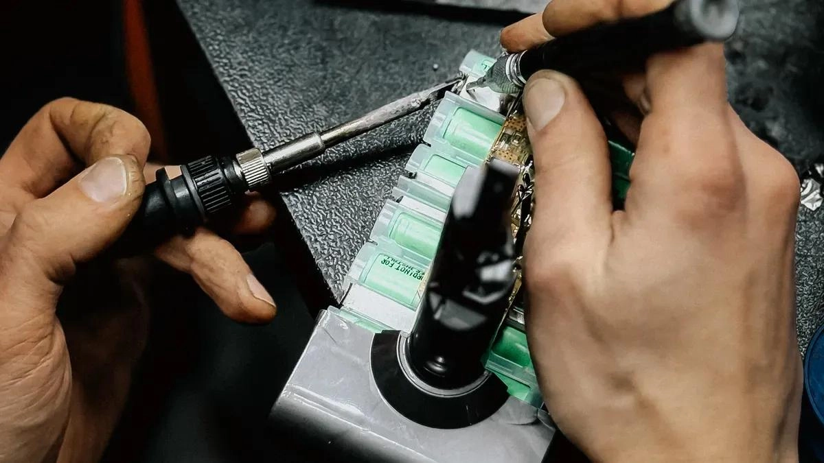
Installers often exert excessive mechanical force onto the illuminated surfaces of flex strips during mounting. Applying direct pressure onto individual diode packages transfers physical strain straight into delicate solder joints. Flexing PCB materials near sharp edges fatigues external solder fillets and cracks internal wire bonds. The 15-25μm gold wire bond represents the weakest internal mechanical connection. Shearing forces easily detach this fragile connection during aggressive installation handling.
Root Cause of Failure | How It Manifests When Bending Around Edges | Key Mechanism/Weak Point |
PCB Flexing | Stress transmitted directly into LED packages placed near the bend/edge. | Bending forces cause solder joint fatigue cracks and can lift or crack delicate internal wire bonds. |
Solder Joint Cracks | Intermittent flickering or complete failure after bending. | Cyclic mechanical stress from flexing fatigues the solder fillets, especially at package corners. |
Gold Wire Bond Breakage | Touch-sensitive operation, flickering, or open circuit when flexed. | The wire bond (15-25μm gold wire) is the weakest mechanical link; flexing applies shear/ tensile stress causing detachment or fracture. |
CTE (Coefficient of Thermal Expansion) Mismatch | Failure may appear or worsen with temperature changes after bending. | Bending can initiate micro-cracks; subsequent thermal cycling causes different materials (chip, wire, PCB) to expand/contract at different rates, worsening the damage. |
Systematic mechanical stress compromises physical safety and leads to several visible optical failures. Installers must identify operational defects quickly during initial testing procedures.
· Intermittent open circuit: The led works sometimes but cuts out randomly, especially if the bend alters the stress state.
· Vibration/flex-induced flicker: The led blinks or flickers when the flex strip is bent, tapped, or subjected to vibration.
· Touch-sensitive operation: Pressing near the led or on the bent area causes the led to turn on or off.
· Position-dependent failures: Failures are concentrated near board edges or in sections that experience the most deformation during bending.
Sharp corners compromise both internal electrical pathways and external weatherproofing. Excessive structural force creates tiny micro-cracks inside copper trace layers. Rainwater seeps into hand-soldered joints when exterior housings rupture under strain.
Stressor | Effect on Component | Consequence |
Physical stress (bending around corners/curves) | Micro-cracks form in copper traces | Premature lighting failure, unlit sections |
Moisture (rain) | Seeps into hand-soldered joints | Compromised IP integrity, waterproofing destroyed |
The S-Type zigzag design allows flat horizontal bends, maintaining a continuous weatherproof seal and eliminating trace cracking. Technicians preserve electrical safety by enforcing a correct bending radius across all led neon rope lights. Maintaining proper bending curves prevents conductor micro-cracks during long-term operational use. Installers choose durable led neon rope lights to prevent permanent physical damage. Following standardized layout guidelines protects both silicone seals and copper conductors. High-quality led neon rope lights maintain complete weather protection when technicians avoid sharp manual folds.
Technicians maintain system durability by implementing best installation practices along complex structural perimeters. Field crews pre-measure architectural reveals before mounting hardware to confirm dimensions. Crew members select rigid aluminum tracks for straight linear runs and flexible silicone channels for continuous sweeping contours. Installers integrate solderless corner connectors to navigate sharp 90-degree transitions without causing dynamic mechanical strain. Mounting tracks provide uniform structural backing that prevents profile sagging across long spatial spans. Spacing mounting clips at regular intervals secures the housing firmly against building walls. Proper clip alignment reduces physical bending tension across corner junctions.
Technicians protect delicate internal diodes by avoiding direct physical pressure on illuminated surfaces during mounting. Installers apply physical force exclusively to side silicone flanges or rigid mounting tracks. Exerting direct downward force onto surface chips risks internal bond wire disconnection and immediate package failure. Careful manual placement ensures smooth optical distribution without physical damage during the installation process. Utilizing 3d bending led flex profiles simplifies multi-axis routing along complex architectural corners. Proper installation around physical building borders requires structured clip placement to preserve optical alignment. Mounting teams verify mechanical clearance across every channel joint before final attachment.
Planning layout details prevents water ingress and voltage drop problems on exterior structures. Technicians complete a thorough design evaluation before securing any mounting hardware. Field crews execute a structured prep sequence:
1. Measure space twice before peeling any adhesive backing from the channel.
2. Map exact physical locations for power sources, dimmers, and main system controllers.
3. Mark physical corners, sweeping curves, and spliced connection points along architectural edges.
4. Draw a quick diagram showing your layout, including where the power supply connects, where dimmers or controllers sit, and how the strips will bend or transition around edges.
Use IP65 or higher for outdoor or damp areas like kitchens and bathrooms.
Exterior architectural lighting installations demand rigorous weatherproofing protocols to prevent serious electrical safety hazards. Field crews apply clear silicone sealant or adhesive-lined heat-shrink tubing at cut points. Technicians protect outdoor splice connections with IP67-rated connectors or marine-grade heat-shrink tubing sealed with silicone. Main power supply drivers reside inside NEMA 3R weatherproof enclosures with sealed cable glands. Maintenance teams in coastal areas double-seal every connection point against salt air corrosion and inspect components annually.
IP Rating | Protection Level | Suitable Application |
IP67 | Dust-tight; can handle temporary water immersion | Gardens, pathways, ground-level installations |
IP68 | Dust-tight; designed for continuous water immersion | Pools, fountains, underwater lighting |
Achieving true IP68 protection requires resin potting inside an aluminum channel. Technicians position led neon rope lights inside the track and pour liquid two-part polyurethane resin until full coverage occurs. Polyurethane resin provides exceptional toughness and UV stability without yellowing or remaining soft. This solid block resin potting process eliminates internal air voids so water cannot enter. Field technicians deploy led neon rope lights along high-moisture perimeters using these potted channels. Sealed led neon rope lights resist standing moisture and temporary submersion effectively. Properly encapsulated led neon rope lights enhance architectural lighting layouts around difficult edges. Implementing systematic weatherproofing protocols protects every architectural lighting installation against environmental degradation while maintaining complete operational safety.
Technicians achieve damage-free architectural lighting by pairing specialized corner accessories with strict physical limits. Preserving the 1-inch minimum bending radius protects internal circuit layers against mechanical stress. Workers must avoid applying direct pressure onto surface diode packages. Physical force cracks internal bond wires and triggers premature system failure. Modular corner links route led neon rope lights around sharp turns safely.
Field crews ensure long-term performance through systematic pre-mounting procedures. Installers dry-fit all mounting channels and corner clips along architectural edges prior to final adhesive attachment. Testing electrical continuity before applying weatherproofing sealant prevents costly rework. This structured procedure guarantees proper installation across complex building facades.
Installers must maintain a minimum bending radius of at least 1 inch (25 mm). The IPC-2223 standard governs flexible printed circuit design. Respecting physical thresholds prevents micro-fractures inside copper trace layers during shaping.
Technicians must never fold led neon rope lights directly at sharp right angles. Manual tight folds destroy internal circuit pathways. Instead, workers use solderless corner connectors or modular junction tracks to route lighting around sharp architectural edges cleanly.
Installers apply mounting pressure exclusively to side silicone flanges or support tracks. Pressing directly on surface-mounted packages detaches fragile gold wire bonds. Careful physical handling guarantees optimal long-term led performance throughout the installation phase.
Field crews apply clear silicone sealant or adhesive-lined heat-shrink tubing over exposed cut points. Potted aluminum tracks with liquid resin provide complete protection against water ingress. These sealing protocols preserve IP-rated architectural lighting reliability in demanding outdoor environments.
Please provide the following detailed information so that our business representatives can better understand your needs and get in touch with you as soon as possible.