
 EN
EN
 English
 繁体中文
繁体中文 Italian
 Greek
Greek Spanish
 Hebrew
 Japanese
 Portuguese
 Korean
 Russian
 French
 German
 Arabic
Blog & Events
Follow NOVANEON for more valuable information to know early
Follow NOVANEON for more valuable information to know early
Oct 13Source: Views: 2
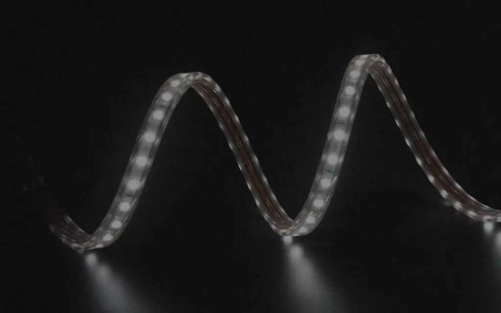
An LED flex strip glows brightly near its power supply. The far end fades, shifts color, or flickers. This symptom signals voltage-drop, which worsens as runs get longer. The fix combines five methods: 24V power, thicker copper wire, parallel wiring, power injection, and shorter powered segments. Two numbers guide every decision. The formula is V = I x R. Here V represents voltage loss, I stands for current in amperes, and R is the round-trip wire resistance in ohms. A 20% power supply safety margin is the second. NOVANEON's Ultra-long LED Flex handles extended runs. Correct wiring remains essential. This guide provides a practical, step-by-step approach to any ultra-long led flex lighting system project.
· Calculate voltage drop before buying components. Use the formula V = I x R. This prevents undersized wiring. It prevents dim strips.
· Choose 24V over 12V for long runs. This halves current draw for the same wattage. Lower current reduces voltage drop.
· Use parallel wiring for strip sections. Each section connects directly to the power supply. This prevents daisy-chain voltage loss.
· Divide long runs into shorter power zones. Each zone receives its own feeder line. Lower current per zone reduces voltage drop.
· Use power injection at several points along the strip. This method delivers steady power. It keeps brightness uniform from end to end.
· Use thick copper wire for feeder lines. Place power supplies close to the strip. These choices reduce voltage drop.
· Size the power supply with a 20% safety margin. Load the unit to 80% capacity. This protects the driver from overheating.
· Check far-end voltage with a multimeter after installation. This reading confirms correct voltage. It catches wiring mistakes early.
A 24V system draws half the current of a 12V system delivering the same wattage. This relationship follows Ohm's law. Lower current means lower resistive losses along the copper traces. The table below summarizes the difference.
Voltage | Current Draw for Same Wattage |
24V | Half the current of a 12V system |
12V | Twice the current of a 24V system |
A 24V strip therefore maintains consistent brightness across a much longer continuous run before voltage-drop becomes noticeable. For runs exceeding roughly 16 feet, 24V is advised because it offers greater flexibility and consistent brightness. NOVANEON's Ultra-long LED Flex series is a purpose-built option for extended lengths. It reduces connection points and power injection requirements.
Power injection means feeding power at multiple points along the strip instead of only at one end. This method counteracts voltage drop on long runs. A 24V strip needs fewer injection points than a 12V strip of equivalent length and output. The lower current in a 24V system produces substantially less resistance-induced voltage loss over the same distance.
Installers should not simply chain strips end-to-end. The total run from a single power supply cannot exceed the recommended maximum without voltage drop occurring. Power injection extends the effective run length. It keeps brightness uniform across the entire installation.
Power distribution divides a long run into shorter, independently fed zones. Each zone receives power from a nearby feeder line. This approach shortens the distance that current must travel through the strip's copper traces. Shorter distances mean lower resistance and less voltage loss.
A 24V system supports longer zones than a 12V system. This reduces the total number of injection points required. NOVANEON's Ultra-long LED Flex series supports extended distances with stable output. It reduces the number of injection points needed for an ultra-long led flex lighting system. Proper power supply capacity and wiring still matter. Installers should calculate voltage drop before buying components.
Every LED flex strip contains thin copper traces that carry current along its length. These traces possess electrical resistance. As the strip grows longer, total resistance climbs. Current must travel farther through more opposition. This opposition converts electrical energy into heat, and the far end receives lower voltage.
Conventional LED strips struggle with this problem. They require frequent power injection points to maintain uniform brightness. NOVANEON’s ultra-long LED flex products solve this differently. They minimize connection points while sustaining stable brightness across extended runs.
Copper trace resistance depends on material quality and cross-sectional area. Thicker copper offers lower resistance per meter. Wider traces reduce voltage loss over any given distance. Even good copper, however, still has resistance. Installers must respect maximum run lengths, use higher-voltage supplies, feed power from both ends, and select thicker feeder wire.
The most visible symptom of voltage-drop is uneven brightness. The strip glows brightly near the power source. Toward the far end, the light dims steadily. As voltage decreases, each LED receives less power. Light output falls proportionally.
Color shift accompanies the fade. White LED emitters change hue when forward voltage changes. A strip that appears pure white at the beginning looks warm or yellow at the end. This inconsistency ruins architectural lighting. A facade with gradual tint changes looks unprofessional.
Flickering may also appear. When the available voltage nears the minimum required by the led driver, output becomes unstable. The flicker might be subtle, but cameras and motion sensors detect it. Preventing the voltage drop in the first place is the only reliable remedy.
Resistive power loss in LED circuits generates unwanted heat. Copper traces carrying heavy current warm up quickly. Reducing resistive loss lowers heat generation directly. Low-resistance components in high-current paths, such as MOSFETs with low RDS(on), minimize voltage drop and operational heat. These components appear in well-designed drivers, but installation conditions remain crucial.
As strip length increases, voltage drops steadily due to copper trace and supply wire resistance. This drop stresses the led driver. The driver works harder to maintain rated current. Extra effort shortens product lifetime and raises operating temperature. Driver efficiency matters. Efficient switching topologies waste less energy as heat than inefficient linear regulators.
Heat threatens an ultra-long led flex lighting system. It accumulates in the strip and inside the driver enclosure. Excessive heat accelerates LED emitter degradation. It also damages solder joints and insulation over time. A hot system fails prematurely.
Prevention follows simple rules. Respect the maximum strip length for the chosen voltage. Use 24V systems rather than 12V. Feed power from multiple points. Choose thick copper feeder wire. These measures reduce resistive loss, keep temperatures controlled, and protect both LEDs and the driver.
Ohm's law provides the foundation for every voltage-drop calculation. The relationship states that voltage loss equals current multiplied by resistance. For a simple circuit, a reader multiplies the current in amperes by the conductor resistance in ohms. The result gives the voltage lost along that conductor. This basic relationship expands into a more practical form for LED strip installations. The industry-standard formula for low-voltage LED systems is VD = (2 × L × I × R) / 1000. In this equation, VD represents voltage drop in volts, L stands for one-way conductor length in feet, I is current in amperes, and R is conductor resistance in ohms per 1000 feet. The factor of 2 accounts for both the supply and return conductors in a complete circuit.
A common mistake involves entering round-trip distance into the formula. The formula already includes the factor of 2 for the return path. If a reader enters round-trip distance, the calculation shows twice the actual voltage-drop. The correct approach uses one-way distance for L. Current must travel to the load and return to the source. This round trip doubles the effective resistance. Installers who forget this detail overestimate voltage loss and may oversize components unnecessarily. Others who ignore the return path entirely underestimate losses and face dimming at the far end. The formula handles this automatically when L represents one-way length.
The datasheet provides the starting point for every calculation. Readers should locate the wattage per metre specification for their chosen strip. This figure drives both led strip wattage estimates and safe run length determinations. A strip rated at 4 watts per foot consumes 4 watts for every foot of length. Multiply this value by the total run length to find the total electrical load. For example, a 50-foot strip at 4W/ft produces a full-load wattage of 200W. The calculated current then follows from the system voltage. A 200W load on a 24V system draws approximately 8.3A. This calculated current feeds directly into the voltage-drop formula. The same wattage per metre figure also determines power consumption per metre for energy budgeting. Installers who skip this step cannot size power supplies or feeder wires correctly.
Voltage determines how far a strip can run before power injection becomes necessary. The table below summarizes the maximum recommended run lengths before voltage-drop becomes noticeable.
Voltage | Maximum recommended run before power injection |
5V | 1–2 m |
12V | 5 m |
24V | 10–12 m |
These figures assume a typical strip load. Higher wattage per metre shortens these distances. Lower wattage extends them slightly. The pattern is clear: higher voltage supports longer runs. A 24V system reaches roughly twice the distance of a 12V system before requiring additional power feeds. This advantage explains why 24V is the preferred choice for ultra-long led flex lighting system projects.
Industry standards provide additional guidance. The NEC recommends a maximum voltage drop of 3% for branch circuits and 5% for the combined feeder and branch circuit. For 12V low-voltage LED strip systems, a 3% drop equals only 0.36V. This small loss can cause visible dimming. Many professionals target under 2% for consistent brightness. The industry standard for low-voltage lighting is to keep every fixture within 10% of the transformer's rated output voltage. On a 12V system, no fixture should drop below 10.8V.
A worked example clarifies the process. Consider a 50-foot 24V strip using 4W/ft. The total load is 200W. The current is about 8.3A. Assume the installer uses 12 AWG wire with a resistance of 1.98 ohms per 1000 feet. The one-way length is 50 feet. The voltage-drop formula gives VD = (2 × 50 × 8.3 × 1.98) / 1000. This equals approximately 1.64V. The supply voltage is 24V. The far end receives about 22.36V. This value stays well within the acceptable range. A 12V system with the same load would draw 16.6A and lose twice the voltage. The 24V system clearly performs better.
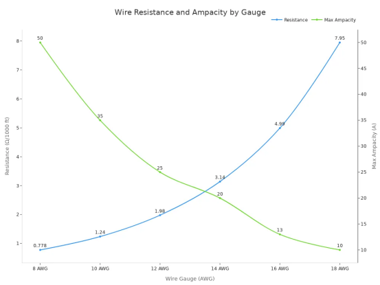
The chart below shows how wire resistance and maximum ampacity vary by wire gauge. Installers use this data to select feeder wires that minimize voltage-drop.
Wire Gauge (AWG) | Resistance (Ω/1000 ft) | Max Ampacity |
8 AWG | 0.778 | 50A |
10 AWG | 1.24 | 35A |
12 AWG | 1.98 | 25A |
14 AWG | 3.14 | 20A |
16 AWG | 4.99 | 13A |
18 AWG | 7.95 | 10A |
Heavier gauge wire offers lower resistance and higher current capacity. A 12 AWG wire carries 25A with a resistance of 1.98 ohms per 1000 feet. An 18 AWG wire carries only 10A with a resistance of 7.95 ohms per 1000 feet. The difference is substantial. Installers should always match wire gauge to the calculated load and the one-way distance. Five methods reduce voltage-drop: use a larger cable cross-section, reduce cable length, distribute the power supply closer to the load, add appropriate power injection points, and design power distribution based on actual load and voltage-drop requirements.
Sizing a power supply begins with one number: the total wattage required by every strip in the installation. A reader multiplies the strip's wattage per metre by its total length. A 4-metre run of a strip rated at 10 W/m consumes 40 watts. This figure represents the full-load wattage for that single run.
Multiple runs demand a different approach. The installer calculates each strip's wattage individually, then sums all values to obtain the total strip wattage. Four separate 5-metre runs of a strip rated at 9.6 W/m produce 48 watts each. The combined load reaches 192 watts. This total strip power drives every subsequent decision about the led driver and wiring.
A common question asks how many led strip lights can I run from one supply. The answer depends entirely on this sum. The total strip wattage must stay below the safe capacity of the chosen unit. Voltage matching is equally critical. All strips must share the same voltage as the driver. Mixing 12V and 24V strips on one supply will damage components.
The calculation also answers how many led strips a power supply can handle in parallel. Each strip connects directly to the driver outputs. Installers never daisy-chain strips end-to-end. This parallel arrangement keeps current draw balanced across all runs.
A power supply should never operate at its maximum rating continuously. The industry-standard 80% rule keeps the total strip wattage at or below 80% of the unit's rated output. This practice provides a safety buffer against overheating, premature failure, and tripped protection circuits.
The table below summarizes the two common derating standards.
Derating Standard | Safety Buffer | Shortcut Formula for Minimum PSU Size |
80% Rule (most common) | 20% | Total Strip Wattage × 1.25 |
90% Rule (high-efficiency) | 10% | Total Strip Wattage × 1.11 |
The 20% safety margin delivers measurable benefits. A unit running at 70–80% capacity produces less heat than one running at 95%. Heat degrades electronic components over time. A properly sized supply therefore lasts longer. Efficiency also peaks near 80% load, which minimizes wasted energy. Headroom helps the driver manage minor voltage fluctuations from the main power line. Stable DC voltage supports consistent LED color and extends emitter lifespan.
Load your supply to no more than 80% capacity. This accounts for heat buildup, efficiency losses, and longevity. High-end supplies might handle 90%, but stick to 80% for safety.
A practical example clarifies the math. A 100W strip load needs at least a 125W supply. The installer multiplies total wattage by 1.25 to add the 20% safety margin. The shortcut formula driver wattage = w/m × total metres × 1.25 captures this relationship. An equivalent expression is driver size = w/m × metres × 1.25. Both produce the same required power supply wattage.
The four-run example from earlier illustrates the full process. The total load is 192 watts. Dividing by 0.8 gives 240 watts. The installer selects a standard unit rated 240W or higher, such as a 250W or 300W model. This required power exceeds the raw load by a comfortable margin.
Manual led strip wattage calculation leaves room for arithmetic errors. An led strip wattage calculator automates the process and cross-checks the result. These tools accept inputs for strip length, wattage per metre, and supply voltage. They output the total load and the recommended power supply rating.
The verification workflow follows a logical sequence. First, calculate each strip's wattage using the formula strip_watts = watts_per_metre × strip_length. Second, sum all strip wattages to obtain the total load. Third, determine the supply's safe capacity using safe_watts = PSU_watts × margin_factor, where the margin factor is typically 0.8. Fourth, confirm that total_strip_watts ≤ safe_watts.
A calculator also helps answer how many led strip lights a given supply supports. The user enters the supply's rated wattage and the strip specifications. The tool returns the maximum total metres allowed. This maximum length calculation uses the formula: Meters = (Supply W × 0.80) ÷ W/m. The result tells the installer exactly how far the strip can extend before exceeding safe loading.
The led strip wattage figure appears throughout these calculations. It determines the total strip power, the required power, and the final driver selection. Installers who verify their math with a calculator catch mistakes before purchasing components. This step saves both time and money on an ultra-long led flex lighting system project.
Series wiring connects strip sections end to end. Current travels through the thin copper traces of every preceding section. Each splice adds resistance. The far end receives less voltage. This approach starves the final meters of an ultra-long led flex lighting system.
Parallel wiring changes the architecture. Each strip section connects directly to the power supply or a distribution block. Current no longer flows through neighboring sections. Voltage stays consistent across the entire run. The table below compares two effective parallel topologies.
Parallel Wiring Topology | How It Minimizes Voltage Drop |
Hub / T-method layout | Moves the power distribution point closer to the fixture group, shortening the long daisy-chain segment that carries the combined downstream load. |
Multiple home runs | Divides one large load into several smaller circuits (e.g., splitting a 120W branch into three 40W runs), reducing current on each cable so a low-voltage system stays practical. |
Voltage drops across long traces can reduce brightness at the far end in large LED arrays. Minimize this effect with a star or grid topology instead of daisy-chaining. Alternatively, increase trace width or copper thickness (e.g., 2oz instead of 1oz) to lower resistance.
Star wiring, also called home-run injection, gives each strip piece its own dedicated wire pair back to a single high-power supply or distribution block. No strip section feeds the next through its copper traces. Thick, low-resistance wires deliver power directly to the strip's copper pads at several locations. Brightness no longer depends on distance. A 20-meter strip can shine as uniformly as a 1-meter piece.
Power injection feeds voltage at multiple points along the strip. The interval depends on system voltage and the strip's wattage per metre. Standard intervals run roughly 3–5 meters for 12V strips and 5–10 meters for 24V strips. Higher wattage per metre shortens the safe distance between injection points.
NOVANEON's Ultra-long LED Flex series supports extended distances with stable output. This reduces the number of injection points needed.
Each zone receives its own feeder line, a thick, low-resistance cable running from the supply to the strip's power pads. Separate feeders deliver these benefits:
· Shorter low-voltage cable runs
· Less voltage drop
· Easier fault finding
· Lower current through each splitter
· More flexible control
· Easier replacement of individual parts
· Prevents the entire wall from depending on one power supply; a single zone fault leaves the rest operating
· Each zone stays electrically separate unless equipment is designed for current sharing
Dividing the lighting into separate power zones in larger installations improves reliability, reduces voltage drop, and eases future maintenance.
Feeder lines simplify voltage-drop calculation. Each zone handles its own load rather than the total installed length. This keeps current lower on every cable.
Feeder wire selection depends on two variables: the calculated current and the cable distance. Installers should not size feeder wires from strip length alone. The published 32.8 ft (10 m) maximum continuous strip run is a strip-length limit. It does not represent a feeder-wire distance allowance or a guarantee of zero voltage drop. A longer feeder cable adds resistance regardless of how short the strip itself may be.
The full path from the led driver or controller to the strip connection matters. For feeder runs up to 20 m, installers apply the same criteria across the entire path. They match the wire gauge to the current rating and to the connector fit, conductor count, polarity, and sealing requirements of the system. A wire that carries the current safely may still fail to fit the connector or may not seal properly in outdoor conditions.
Wire Gauge (AWG) | Resistance (Ω/1000 ft) | Max Ampacity |
10 AWG | 1.24 | 35A |
12 AWG | 1.98 | 25A |
14 AWG | 3.14 | 20A |
16 AWG | 4.99 | 13A |
18 AWG | 7.95 | 10A |
Heavier gauge wire lowers resistance and raises current capacity. A 10 AWG feeder carries 35A with a resistance of 1.24 ohms per 1000 feet. An 18 AWG feeder carries only 10A with a resistance of 7.95 ohms per 1000 feet. The difference is substantial over long distances.
Power supply placement determines how far current must travel before reaching the strip. A centrally located unit forces long feeder runs in multiple directions. A distributed layout places the unit closer to each load. Shorter feeders mean lower resistance and less voltage drop.
Installers should divide longer installations into separate parallel runs fed from the appropriate power or control point. They should not extend a single run beyond its documented limit by simply adding a larger led driver. A larger driver does not reduce the resistance of the copper traces inside the strip. It only supplies more current to a circuit that already loses voltage along its length.
NOVANEON offers customization of operating voltage, control protocols, and IP ratings such as IP65, IP66, and IP68. These options affect power supply placement for outdoor projects. A unit rated for outdoor use may sit closer to the strip, which shortens feeder runs and reduces voltage loss.
Power zones divide a large installation into smaller, independently fed circuits. Each zone receives its own feeder line from a distribution point. This arrangement keeps current lower on every cable. It also simplifies voltage-drop calculation because each zone handles its own load rather than the total installed length.
Balanced zones prevent one circuit from carrying more current than its feeder wire can handle safely. The installer calculates the led strip wattage for each zone, sums the values, and confirms that the total stays within the capacity of the chosen led driver. A 20% safety margin on the driver rating provides headroom for heat buildup and minor voltage fluctuations. Zones also make fault finding easier. A single zone fault leaves the rest of the installation operating.
A multimeter provides the fastest diagnostic tool for voltage problems. Before sealing or concealing wiring, technicians measure voltage at the far end of the strip. This reading reveals whether the system delivers adequate power across the entire run. A reading within the strip's operating range confirms proper voltage delivery. A low reading indicates excessive voltage-drop along the circuit.
Preventive maintenance relies on this same measurement. Technicians check voltage consistency along the strip, especially for longer setups. They compare readings at the power feed point and at the farthest LED. A significant difference between these two values points to resistance buildup in the copper traces or feeder wires. Catching this issue early prevents permanent brightness loss and color shift.
Loose connections interrupt electrical flow and cause sections to flicker or dim intermittently. Cheap snap-on connectors are a common source of unstable electrical contact. Technicians should inspect every splice and connector for tightness and corrosion. Damaged wires or poor solder joints require immediate replacement.
Polarity errors also produce malfunction. Reversed positive and negative leads prevent the strip from lighting at all or cause erratic behavior. Installers verify polarity at every connection point before applying power. They also check that connectors match the strip's voltage and current ratings. A connector rated for lower current may overheat and fail under load.
An undersized power supply cannot deliver stable voltage and current. When a unit operates near or beyond its maximum capacity, flickering, dimming, or uneven brightness results. Power supplies should operate at only 70%–80% of rated capacity. A 24V LED strip drawing 60W should not pair with a 60W driver. Running a driver at 100% load causes overheating. A 20% buffer is recommended, so a 75W minimum load calls for a 96W–100W unit.
Mismatched dimming equipment ranks as the leading cause of flickering, buzzing, and premature driver failure. Not all dimmable LED drivers work with all dimmer switches. Connecting a non-dimmable driver to a dimmer switch typically results in flickering, buzzing, overheating, or silent driver failure. Installers should verify compatibility before installation.
Adding power injection points solves voltage-drop on long runs. Using 24V systems, dual-end power supply connections, or parallel wiring improves lighting uniformity and stability over long distances. Each individual run should stay within its recommended length to avoid dimming at the ends.
Successful ultra-long runs depend on five choices: 24V power, parallel wiring, power injection, heavy copper feeders, and a 20% safety margin on the supply. Installers should calculate voltage drop before purchasing components. They need the strip's wattage per metre and the safe run length for the chosen voltage. NOVANEON's Ultra-long LED Flex series reduces connection points, yet proper supply capacity and wiring remain essential.
A simple pre-install checklist keeps the project on course:
1. Measure strip wattage per metre.
2. Calculate total load.
3. Divide into power zones.
4. Mark injection points.
5. Choose wire gauge.
6. Install.
7. Verify far-end voltage.
These steps protect brightness, color accuracy, and driver lifespan. An ultra-long led flex lighting system performs reliably when installers respect its electrical limits.
A few questions recur on every ultra-long LED installation. Short, direct answers follow.
Copper traces inside the strip carry both current and resistance. Longer traces generate higher total resistance. Current traveling through that resistance loses voltage, exactly as V = I × R predicts. The far end receives less power, so brightness fades and white light shifts toward warm yellow hues.
A typical 24V strip supports a 10–12 meter run without extra power feeds. A 12V system reaches roughly 5 meters. A 5V strip manages only 1–2 meters. Higher wattage per meter shortens every distance. Installers should confirm the strip's actual power draw before choosing a run length.
Standard intervals fall at 3–5 meters for 12V strips and 5–10 meters for 24V strips. The strip's wattage per meter sets the exact spacing. High-power strips demand shorter intervals. NOVANEON's Ultra-long LED Flex series extends these distances, reducing the number of injection points required.
Installers should match gauge to current and distance. A 12 AWG copper feeder carries 25A at 1.98 ohms per 1000 feet. An 18 AWG wire carries only 10A at 7.95 ohms per 1000 feet. Heavier gauge reduces resistance. Use the lowest-resistance wire the connector accepts.
Total strip wattage equals watts per meter multiplied by total length. Divide that figure by 0.8. A 100W strip load, for example, needs a 125W supply. This 20% safety margin protects the driver from heat buildup and premature failure.
The series minimizes connection points and maintains stable output across extended runs. The installer still sizes the power supply and feeder wire correctly. Every project needs the strip's wattage per meter and a voltage-drop calculation before installation begins.
Please provide the following detailed information so that our business representatives can better understand your needs and get in touch with you as soon as possible.