
 EN
EN
 English
 繁体中文
繁体中文 Italian
 Greek
Greek Spanish
 Hebrew
 Japanese
 Portuguese
 Korean
 Russian
 French
 German
 Arabic
Blog & Events
Follow NOVANEON for more valuable information to know early
Follow NOVANEON for more valuable information to know early
Aug 27Source: Views: 199
A homeowner finishes a 30-foot LED strip lights installation, only to watch the final ten feet glow dimly. The white LEDs shift to a dull yellow. Frustration sets in, and many assume the product is defective. This scenario is not a failure of the LED light strips themselves. It is a predictable electrical phenomenon called voltage drop—and the key to solving it is to avoid voltage drop from the start.
Common symptoms of voltage drop in LED strip lighting include:
·Dimmer LEDs near the end of the strip
· Color shifting, particularly in RGB strips (red may dominate as blue and green fade)· Uneven brightness, especially noticeable in white LED strips
· Flickering under load
This article explains the science behind voltage drop and offers proven solutions, from upgrading to 24V systems to strategic power injection. These methods ensure uniform brightness across any length and help you avoid voltage drop before it ever becomes a problem. By the end, readers will have a clear action plan to fix and prevent this issue permanently, ensuring their LED strip lighting performs flawlessly.
Voltage drop describes the gradual decrease in voltage along the length of led strip lights. This phenomenon occurs due to the inherent resistance of the copper traces and supply wires. Think of water pressure in a long garden hose. Water flows easily at the faucet, but pressure drops considerably by the time it reaches the far end. The causes of voltage drop are straightforward: resistance increases with distance, and every wire and copper trace adds resistance to the circuit.
The resistance of copper traces in an LED strip is directly proportional to its length. As the length increases, resistance increases, and voltage drop becomes more significant. This explains why long led strip runs often show dimmer LEDs at the far end. The voltage available to the LEDs decreases as current travels through the strip.
The table below shows how wire gauge and PCB copper thickness affect voltage loss.
Factor | Recommendation | Impact on Voltage Loss |
Wire gauge | Use 14 AWG or 12 AWG instead of 18 AWG for long runs | Thicker wires have less resistance; doubling wire thickness can reduce voltage loss by half |
PCB copper layer | Look for 2 oz or higher copper thickness | Thicker copper traces reduce resistance, directly minimizing voltage loss along the strip |
Why do 12V strips fail beyond 5 meters while 24V strips can run twice as long? The answer lies in current. For the same power output, a 12V system draws twice the current of a 24V system. Higher current increases voltage drop proportionally.
System Voltage | Maximum Recommended Run Length | Reason |
12V | ~5 meters (16.4 feet) | Voltage loss becomes significant beyond this length |
24V | ~10 meters (32.8 feet) | Lower current draw reduces voltage loss, allowing longer runs |
The first symptom of trouble is dimming at the far end. Then white LEDs shift to a warm or yellow hue. This color shift occurs because different colored LEDs require different forward voltages. When voltage drops below the threshold for blue or green LEDs, they dim or turn off, leaving red to dominate. This understanding helps designers avoid voltage drop in new installations.
To understand the numbers, consider this calculation:
The voltage loss formula is V_loss = I × R, where I is current in amperes and R is resistance in ohms.
For 18 AWG copper wire, resistance per meter is approximately 0.021 Ω.
For a 10-meter run (including return path), total resistance is about 0.21 Ω.
Assuming a current of 1.5A for a 5-meter LED strip, the voltage loss is 1.5A × 0.21Ω = 0.315V.
This 0.315V loss represents about 2.6% of a 12V supply, which is generally acceptable.
However, longer runs or thinner wires can cause voltage losses exceeding 5%, leading to visible dimming at the far end.
This calculation shows why understanding the causes of voltage drop helps designers plan long runs of led strip lights. The combination of distance, wire gauge, and system voltage determines whether a long-distance installation will perform uniformly.
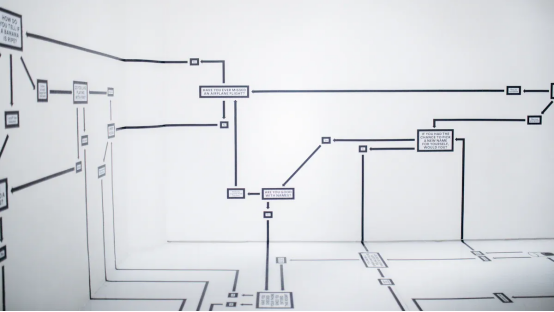
The fundamental formula for calculating voltage drop is straightforward: Voltage Drop (V) = Current (I) × Total Resistance (R). This relationship reveals that two primary variables control the outcome. Current represents the flow of electricity through the circuit, measured in amperes. Resistance encompasses every obstacle that impedes that flow, including the strip's internal copper traces and the supply wires connecting the power source to the strip.
Several factors influence the resistance component of this equation. Conductor size matters significantly—a larger cross-sectional area reduces resistance. Material composition also plays a role, with copper offering lower resistance than aluminum. The length of the run increases resistance proportionally, and temperature affects resistance as well, with higher temperatures increasing it.
The wire gauge directly impacts resistance values. A 10 AWG wire offers approximately 1 ohm per 1000 feet, while a 20 AWG wire presents about 10 ohms per 1000 feet, and a 30 AWG wire reaches roughly 100 ohms per 1000 feet. This exponential relationship means that selecting the proper wire gauge becomes critical for long installations. A decrease of 10 gauge numbers multiplies conductance by approximately 10 times.
Consider a real-world scenario involving a 10-meter 24V led strip drawing 2 amps per meter. The total current for this installation reaches 20 amps. Using 18 AWG supply wires with a resistance of approximately 0.021 ohms per meter, the calculation proceeds as follows. For a 10-meter run including the return path, total wire resistance equals about 0.21 ohms. Multiplying the 20-amp current by this resistance yields a voltage drop of 4.2 volts. This loss represents 17.5% of the 24V supply—a substantial reduction that would cause visible dimming across the led strip lights.
This example demonstrates why designers must calculate voltage drop before installation. The distance between the power supply and the strip's far end directly affects performance. Longer distance requires thicker wires or higher system voltage to compensate.
Several online calculators simplify this process. Dedicated LED strip voltage drop calculators accept 12V and 24V inputs, while general DC calculators handle 48V systems. Professional tools from manufacturers like Bock Lighting emphasize that 12V systems experience noticeable dimming with just a 3% drop (0.36V). These resources recommend heavier gauge wire, shorter wire runs, and multiple power injection points.
Online tools allow professionals to enter wire type, length, voltage, and load to determine the correct wire gauge. These tools streamline the design process and reduce calculation errors.
Understanding the formula helps designers grasp why each solution works. The relationship between current, resistance, and voltage remains constant regardless of the specific installation.
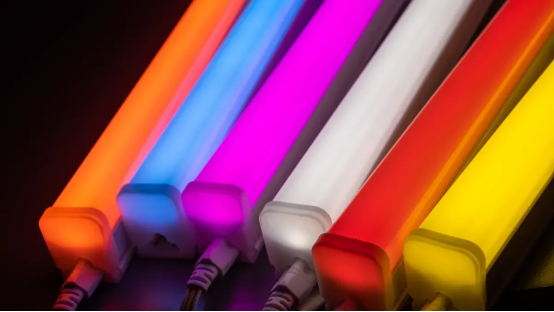
Three proven approaches address the challenge of long LED runs. Each method tackles the underlying physics from a different angle, and installers can combine them for maximum effectiveness. The right choice depends on the project's scale, budget, and performance requirements.
The most straightforward solution involves raising the system voltage. Doubling the system voltage from 12V to 24V halves the current for the same power delivery. Since voltage drop is calculated as V_drop = I × R, halving the current halves the voltage drop in absolute volts. However, because the percentage drop is calculated against the higher 24V baseline, the percentage voltage drop is reduced by 75%, not 50%. This dramatic improvement explains why large off-grid systems overwhelmingly choose 48V for even greater efficiency.
Parameter | 12V System | 24V System |
Current (same power) | 300A | 150A |
Resistance (wire) | 0.0025Ω | 0.0025Ω |
Voltage drop (V) | 0.75V | 0.375V |
Voltage drop (%) | 6.25% | 1.6% |
For most residential projects, 24V strips represent the sweet spot. They support up to 10 meters without additional power injection, which covers typical room perimeters and cove lighting. Commercial or ultra-long runs exceeding 20 meters benefit from 48V systems. These higher-voltage options eliminate voltage drop concerns across large areas without compromising brightness. They also produce less heat and waste less energy, leading to cooler operation and longer lifespan. Traditional low-voltage systems experience voltage drop over long distances, causing dimmer sections. In contrast, 48V systems allow for longer continuous strip runs while maintaining consistent brightness, reducing the need for multiple power injection points and simplifying installation. This results in fewer joins, cleaner installations, and more uniform lighting output.
Power injection offers a practical solution for existing installations that already use 12V strips. This technique involves running parallel wires from the power supply to multiple points along the strip. Powering from both ends represents the simplest form of this approach. For a 50-foot strip, placing the power source in the middle and splitting into two 25-foot sections running left and right effectively halves the distance current travels inside the strip.
The procedure follows a clear sequence. First, calculate total strip length, total wattage, and system voltage. Determine total current using the formula: Total Amps = Total strip wattage ÷ System voltage. Add a 20% safety margin to select the power supply wattage. Second, determine injection points based on voltage: every 5 meters for 12V strips, every 7–10 meters for 24V strips, and every 15–20 meters for 48V strips. Third, select the appropriate wire gauge based on total current on the injection wire. Fourth, expose the copper pads at the injection point and solder wires or use a connector block. Fifth, connect with correct polarity—reversing polarity can destroy the LEDs. Sixth, use a single power supply for all injected sections. Finally, test the installation at full brightness for 10 minutes and verify the far-end voltage remains at least 95% of supply voltage.
Wiring Method | Best For | How It Works | Key Advantage |
Power from Both Ends | Single strips 5–10m (12V) or 10–15m (24V) | Connect power supply to start; run separate wire pair to end pads | Halves the distance current travels inside the strip |
Power Injection in the Middle | Strips longer than 2× max feed length | Inject at the center point with heavy-gauge wire; keep original feed at start | Electrically splits strip into two shorter sections |
Star Wiring / Home-Run | Multiple separate sections across a large area | Each strip section gets its own dedicated wire pair back to a single supply | Complete electrical isolation; one section failure doesn't affect others |
Parallel Bus Line | Super-long seamless runs (e.g., 30m cove) | Run thick main cables parallel to strip; splice pigtails every few meters | Strip pulls current locally from the bus, minimizing voltage drop |
For RGB or RGBW strips, power injectors also compensate for signal degradation. Install a repeater every 10 meters for 12V strips to maintain stable control over 30+ meters. These power injectors regenerate both power and data signals, ensuring consistent color and brightness across the entire run.
Constant current drivers offer a premium alternative. These devices adjust voltage automatically to maintain steady current, eliminating dimming entirely. They work well for long-distance decorative strips, even with thin wires such as 28 AWG. This approach suits critical installations where uniform brightness matters more than cost.
These practical solutions give installers flexibility. Whether upgrading to 24V, implementing multiple power injection points, or choosing constant current drivers, each method addresses the root cause. The key remains planning the installation around the strip's maximum run length specification and positioning the power supply accordingly.
Selecting the correct components for an LED installation requires attention to two critical factors: system voltage and conductor size. Both directly influence voltage drop and determine whether the led strip lights perform uniformly across their full length. The right choices reduce energy waste, simplify installation, and eliminate the need for costly retrofits.
Wire gauge (AWG) directly impacts resistance. A lower gauge number indicates a thicker wire with less resistance. For runs exceeding 10 meters, installers should select at least 18 AWG wire. Projects spanning 20 meters or more demand 14 AWG or thicker. The relationship between gauge and resistance follows a predictable pattern: doubling wire thickness can reduce voltage drop by half.
The table below illustrates how wire gauge and voltage affect maximum run length.
Factor | Effect on Maximum Run Length |
Voltage (12V vs 24V) | 12V strips reach ~16 feet (5 meters); 24V strips reach ~32 feet (10 meters) due to lower current and reduced voltage drop |
Wire Gauge (AWG) | Thicker wires (14 or 12 AWG) reduce resistance, permitting longer runs |
Selecting the proper wire gauge prevents dimming at the far end of the strip. The correct choice depends on total current draw and the distance between the power supply and the strip. Installers should calculate the expected current before choosing wire. This calculation prevents undersized conductors that cause excessive voltage loss.
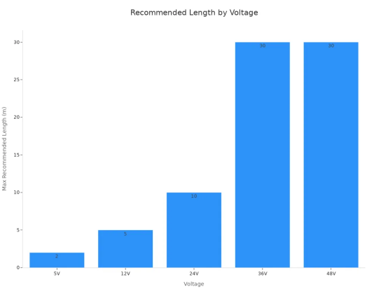
The system voltage determines how far led strip lights can run before voltage drop becomes visible. The chart below shows the maximum recommended length for each voltage option.
Voltage | Maximum Run Length | Best Use Case |
12V | 5 meters | Short runs under 5m, automotive, low cost |
24V | 10 meters | Residential projects 5-15m, most common |
48V | 20 meters | Commercial or ultra-long runs over 15m |
For the same power level, a 12V system draws roughly twice the current of a 24V system. This higher current demands thicker wires, larger connectors, and more power injection points. The 24V option represents the sweet spot for most residential work. It supports runs up to 10 meters without additional feeds. The 48V system suits large-scale projects and long-distance installations, though it requires compatible strips and supplies that cost more.
Installers should always check the strip's maximum run length specification before planning the power supply placement. This simple step prevents voltage drop issues before they begin. The general rule keeps voltage as low as possible for the project while splitting long runs into shorter sections with the power source positioned in the middle.
This journey began with the physics of resistance and ended with practical solutions. This phenomenon is a solvable engineering challenge, not a design flaw. Two takeaways stand out. For new installations, choosing 24V or 48V led strip lights builds in headroom and helps decrease voltage drop. For existing 12V led light strips, power injection at strategic intervals revives LED performance. Understanding voltage level requirements helps avoid voltage drop. Such planning during the design stage prevents costly rework and customer dissatisfaction. A simple pre-calculation eliminates common callbacks and saves labor hours and materials. These two strategies form the core of effective solutions. These solutions prevent issues on LED strips. With these practical solutions, ultra-long LED runs shine with uniform brilliance.
A 12V system typically supports runs up to 5 meters before voltage drop becomes visible. Beyond this length, the far end dims noticeably. The higher current draw of 12V strips accelerates this loss. Installers should plan shorter sections or upgrade to 24V for longer distances.
Thicker wire carries more current with less resistance. A lower AWG number means a thicker conductor. For runs over 10 meters, 18 AWG wire works adequately. Projects spanning 20 meters require 14 AWG or thicker. The correct wire choice reduces voltage loss significantly.
Yes. Power injection adds parallel wires from the power supply to multiple points along the strip. This technique splits the electrical path into shorter segments. For a 12V strip, injection every 5 meters restores brightness. The method works well for retrofitting completed installations without replacing the entire system.
For residential projects up to 15 meters, 24V led strip lights offer the best balance. Commercial installations exceeding 20 meters benefit from 48V systems. Higher voltage reduces current draw, which minimizes voltage drop. The power supply must match the strip's voltage rating exactly.
The distance between the power supply and the strip's far end directly impacts brightness. Longer wire runs add resistance, increasing voltage drop. Placing the power supply near the strip's midpoint halves the effective distance. This simple positioning strategy improves uniformity across the entire led installation.
Please provide the following detailed information so that our business representatives can better understand your needs and get in touch with you as soon as possible.