
 EN
EN
 English
 繁体中文
繁体中文 Italian
 Greek
Greek Spanish
 Hebrew
 Japanese
 Portuguese
 Korean
 Russian
 French
 German
 Arabic
Blog & Events
Follow NOVANEON for more valuable information to know early
Follow NOVANEON for more valuable information to know early
Jul 27Source: Views: 283
People often ask if 3d bending led flex can be safely bent during installation. The answer depends on how closely they follow good practices. Bending the flex without care may cause damage, such as cracked copper traces or broken solder joints. Quality results require attention to practices that protect the led strip, including avoiding sharp folds and using the right guide for corners. Industry reports show that mistakes like twisting the flex or cutting away from marked lines can ruin waterproofing and expose conductors. Careful planning and respect for guidelines help achieve a professional finish.
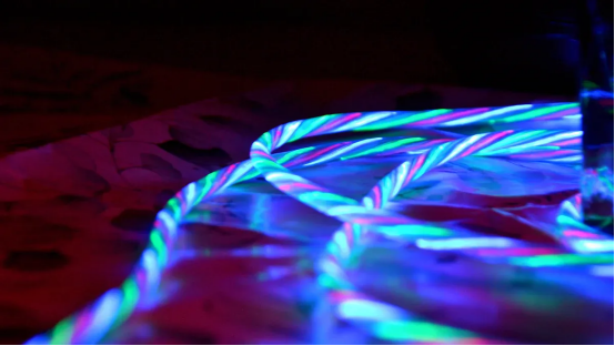
3d bending led flex offers unique versatility for creative lighting projects. This product allows users to shape light in three dimensions, making it ideal for complex designs. Safe bending depends on several factors. Manufacturers design led neon flex and led neon strip products with flexible materials and internal structures that support moderate curves.
To ensure safe bending, users should:
· Check the minimum bending radius specified by the manufacturer.
· Plan the layout before installation to avoid unnecessary adjustments.
· Use gentle, gradual curves instead of sharp angles.
· Keep the led neon flex and led neon strip flat during installation to prevent internal stress.
Tip: Always test a small section of the flex before full installation. This practice helps identify any issues with the chosen bending method.
Proper handling of led neon flex and led neon strip reduces the risk of internal breakage. When users follow these guidelines, they can achieve smooth, continuous lines of light without compromising the product.
Improper bending can lead to serious problems. Excessive force or sharp bends may break the internal circuit or damage the waterproof layer. Users often encounter issues when they twist the flex or ignore the recommended bending radius.
Common causes of damage include:
1. Bending the led neon strip beyond its rated flexibility.
2. Twisting the led neon flex during installation.
3. Forcing the flex into tight corners without using proper connectors.
A damaged led neon strip may show dark spots, flickering, or complete failure. Water can enter through cracks in the waterproof layer, causing further electrical problems.
Note: Once damage occurs, repairs can be difficult and may require replacing the entire section of 3d bending led flex.
Careful attention to bending techniques ensures the longevity and performance of both led neon flex and led neon strip products.
3d bending led flex stands out in the lighting industry for its ability to create dynamic and complex shapes. Designers often select the right led neon flex for projects that require both horizontal and vertical curves. This flexibility allows for creative installations in architectural, retail, and entertainment settings. The structure of led neon flex and led neon strip supports smooth, shadow-free illumination, which ensures even lighting across all angles.
The following table highlights the main features and benefits of these products:
Feature | Benefit |
Horizontal and vertical bending | Enables creation of fully three-dimensional shapes and curves, enhancing design possibilities. |
Smooth, shadow-free illumination | Provides consistent lighting from every angle, ideal for immersive environments. |
3D Bending | Allows for complex installations with both planar shifts and spatial curves. |
High efficiency | Maintains structural integrity and continuous light line in demanding designs. |
Led neon flex and led neon strip both use advanced materials that resist wear and maintain performance over time. When users understand neon flex structure, they can plan installations that maximize both visual impact and durability.
Proper bending techniques play a critical role in the longevity and performance of led neon flex and led neon strip. Incorrect handling can cause several issues:
· Cracked or pinched outer casing
· Damaged LED chips or solder points
· Electrical shorts due to broken wiring
· Uneven lighting with dark spots or flickering sections
· Increased risk of overheating and short circuits
These problems often result from forcing the flex into tight spaces or ignoring manufacturer guidelines. Led neon flex and led neon strip require careful planning to avoid these risks. When installers respect the recommended bending radius and use the correct connectors, they protect the internal components and maintain a continuous line of light. Proper installation ensures that the lighting system remains safe, efficient, and visually appealing for years.
Respecting the minimum bending radius stands as one of the most important good practices when working with 3d bending led flex. Most popular models specify a minimum bending radius between 30mm and 100mm. Installers should always check the product datasheet and choose based on bending radius to ensure quality results. Exceeding the minimum bending radius can cause micro-cracks in the copper traces inside the led neon flex or led neon strip. These cracks may lead to dead pixels, flickering, or even total failure. Repeatedly forcing the flex beyond the recommended bending radius can also result in metal fatigue, which increases the risk of permanent damage.
Tip: Always use a flexible guide or template to maintain the correct minimum bend diameters during installation.
The internal structure of led neon flex and led neon strip includes sensitive electronic components. Matching the polarity before powering on the led is essential to avoid damaging the strip. Incorrect polarity can cause immediate hardware failure. Installers should also ensure the power supply voltage matches the led neon flex specifications, such as 5V, 12V, or 24V. Using connectors instead of direct soldering helps reduce wiring mistakes and protects the internal circuitry. Flexible neon light strips can only be cut at specific intervals, usually marked on the product. Cutting away from these marks can break the circuit and avoid damaging adjacent strips.
Major manufacturers provide clear instructions to help users avoid damage and achieve a professional finish. They recommend turning off power before installation or cutting. Only manufacturer-approved connectors and plugs should be used. Installers should securely mount led neon flex and led neon strip on clean, dry surfaces. Testing the lights before final installation ensures everything works as expected. If unsure about wiring, consulting a qualified electrician is a smart choice. Following these practices helps maintain the integrity of the led neon flex and extends its lifespan.
Sharp bends and twisting often lead to immediate failure in led neon flex and led neon strip installations. When installers twist the strip, they risk snapping internal copper traces and solder joints. Bending the strip too tightly can overstrain the silicone and the internal PCB. This action often results in circuit breaks and dead LEDs. Installers must always respect the minimum bending radius. Ignoring the minimum bending radius can cause permanent damage. The minimum bending radius ensures the flex maintains its structure and function. Each led neon flex and led neon strip comes with a recommended minimum bending radius. Installers should never force the product into a tighter curve than the minimum bending radius allows.
Tip: Always use a template or guide to maintain the correct bending radius, especially around corners.
Cutting led neon flex or led neon strip at the wrong location can cause several problems. Manufacturers mark specific points for safe cutting. Ignoring these guidelines can result in loss of power to subsequent LEDs, dim or non-functioning segments, short circuits, or even complete failure of the strip. Installers must always cut only at the marked intervals. The minimum bending radius also applies after cutting, as improper handling can stress the exposed ends.
· Loss of power to subsequent LEDs
· Dim or non-functioning segments
· Short circuits that could damage the power supply
· Complete failure of the strip
Following the cutting guidelines protects the integrity of the led neon flex and led neon strip and prevents unnecessary damage.
Corners present a challenge in many installations. Some installers try to bend the led neon flex or led neon strip sharply around corners, ignoring the minimum bending radius. This mistake often leads to internal PCB flexing, which stresses solder joints and LED packages. The table below shows frequent mistakes that can occur during installation:
Mistake Type | Description |
PCB Flexing During Manufacturing | Bending PCB panels can stress solder joints and LED packages, leading to failures. |
Improper Handling | Lifting boards incorrectly or stacking them without support can cause flex and stress on components. |
Over-torquing Screws | Excessive pressure from screws can distort the PCB and stress nearby LEDs. |
Aggressive Cleaning or Handling | High-pressure cleaning can damage internal wire bonds, leading to failures. |
Rework Operations | Desoldering and resoldering can introduce thermal and mechanical stress. |
Installers should always use special connectors designed for corners. These connectors help maintain the minimum bending radius and prevent internal stress. Proper use of connectors ensures the led neon flex and led neon strip remain reliable and safe throughout their lifespan.
A successful led neon flex installation starts with careful planning. Installers who want to make perfect curves and avoid damage must understand how to bend led neon flex correctly. The following steps help minimize stress on the flex and ensure proper installation support:
1. Review the manufacturer's specifications for minimum bending radius. This step prevents damage to the PCB and internal components.
2. Place bend areas away from critical components. Strategic placement reduces mechanical stress and protects the led strip.
3. Add stiffeners in sections that need extra support. Stiffeners help maintain the correct radius and prevent unwanted flexing.
4. Mark clear bend zones in the design. These zones should have at least 0.5 mm clearance from copper features to avoid electrical issues.
5. Select materials that match the project's bending and thermal needs. Collaboration with manufacturers ensures the right choice for each installation.
6. Use wider traces and larger spacing in flexible areas. This approach lowers the risk of cracking during curves.
7. Test the layout with 3D simulation tools. Simulations reveal potential problems before the actual installation begins.
Installers should always plan the path of the led neon flex to avoid sharp corners and maintain smooth curves. Good planning ensures that every radius meets the minimum bending radius requirement. This process also helps installers handle corners correctly and avoid unnecessary stress on the flex.
Tip: Sticky backing on the led neon flex makes installation easier. Installers can secure the strip in place before final adjustments, which helps maintain the correct radius and shape.
Proper tools and connectors play a key role in led neon flex installation. Installers should use a flexible guide to maintain the correct bending radius throughout the project. A guide helps create consistent curves and prevents accidental sharp bends. For long runs, gradual insertion of the flex into channels or mounting tracks prevents twisting and protects solder joints from damage.
Special connectors designed for led neon flex allow for clean transitions between sections. These connectors help maintain the minimum bending radius at joints and corners. Installers should avoid direct soldering whenever possible, as connectors provide better support and reduce the risk of damaging the internal wiring.
A table below summarizes essential tools and their functions:
Tool/Connector | Function |
Flexible guide | Maintains correct bending radius and curves |
Sticky backing | Secures flex during installation |
Special corner connector | Handles corners and maintains radius |
Mounting track | Supports long runs and prevents twisting |
Installers who use the right tools and connectors achieve smoother curves and longer-lasting results.
Handling 90-degree corners requires special attention. Installers should never force the led neon flex into a tight angle, as this action exceeds the minimum bending radius and risks damaging the internal structure. Instead, they should use special connectors designed for corners. These connectors allow the flex to transition smoothly around the corner while maintaining the correct radius.
To handle corners correctly, installers should:
· Measure the space and mark the exact location for the bend.
· Use a corner connector that matches the led neon flex model.
· Insert the flex gradually into the connector, ensuring no twisting or pinching occurs.
· Check that the radius at the corner meets or exceeds the minimum bending radius.
Note: Gradual insertion for long runs and corners prevents twisting and protects solder joints from stress.
Installers who follow these techniques avoid dead spots and ensure continuous, even lighting around every corner. Proper handling of the minimum bending radius at corners keeps the led neon flex reliable and visually appealing.
Installers must consider the environment before choosing materials for 3D LED flex installations. Indoor spaces usually provide stable temperature and humidity. Outdoor environments often present extreme conditions. Temperature and humidity can affect the performance and durability of the flex. The choice of material impacts how well the product handles these challenges.
The table below compares common materials used in 3D LED flex for outdoor installations:
Material | Temperature Range | Humidity Resistance | Durability | UV Resistance |
Silicone | -40°C to 220°C | Excellent | Highly durable | Excellent |
PVC | -10°C to 60°C | Moderate | Prone to cracking | Poor |
PU | Varies | Degrades in high humidity | Good | UV-sensitive |
Silicone offers the best performance for outdoor use. It resists cracking and maintains flexibility across a wide temperature range. PVC may crack in cold weather and does not resist UV light well. PU can degrade in high humidity and is sensitive to sunlight. Installers should select silicone for outdoor projects to ensure the flex remains reliable.
Installers must also check the minimum bending radius for each material. Outdoor installations often require longer runs and more curves. The minimum bending radius ensures the flex does not crack or lose its waterproof seal. Installers should avoid placing the flex near sharp corners or areas with frequent movement. Proper mounting and sealing protect the led and maintain the correct radius.
Tip: Always verify the minimum bending radius for the chosen material before starting any outdoor installation.
Different projects require unique approaches to layout and installation. Architectural lighting often uses long, continuous lines. Retail displays may need tight curves and sharp corners. Entertainment venues sometimes demand complex shapes and frequent changes in direction.
Installers must plan each project by mapping out every radius and bend. They should use templates to maintain the minimum bending radius throughout the design. For projects with many corners, special connectors help keep the correct radius and prevent stress on the flex. Installers should avoid forcing the flex into shapes that exceed the minimum bending radius.
The minimum bending radius protects the internal structure of the led. It prevents cracks in the wiring and keeps the light even. Installers should always test a small section before completing the full installation. This step confirms that the flex can handle the required radius and bending without damage.
Note: Careful planning and respect for the minimum bending radius lead to longer-lasting and safer installations.
Careful planning and respect for the minimum bending radius help installers avoid damage and achieve high installation quality. Experts recommend always checking the minimum bending radius, using a guide for each bend, and matching the radius to the project’s needs. For best results, follow this checklist:
1. Confirm minimum bending radius for each flex and led.
2. Use a guide to maintain correct bending radius.
3. Plan cable routing and support structure.
4. Test each section before final installation.
Professional installation ensures long-lasting, seamless results.
Manufacturers specify a minimum bending radius. Most products allow bends between 30mm and 100mm. Users should always check the datasheet before installation. Exceeding this radius can break internal circuits.
Yes, users can cut 3D LED flex, but only at marked intervals. Cutting outside these points may cause segments to fail. Always use a sharp tool and follow the manufacturer's guidelines.
First, check for visible damage or loose connections. Replace damaged sections if needed. If the problem continues, test the power supply and connectors. Seek help from a qualified technician for complex issues.
Material | Outdoor Suitability |
Silicone | Excellent |
PVC | Moderate |
PU | Limited |
Silicone-based flex works best outdoors. It resists UV light and extreme temperatures. Always confirm the product rating before outdoor use.
Please provide the following detailed information so that our business representatives can better understand your needs and get in touch with you as soon as possible.